DESIGN METHOLOGY Design Equations The unit discharge rate q from each of the perforations is governed by the size of the perforation and the static pressure at its respective location along the pipe. The test should not only check the empirical.

Hanbit Soltech Products Packed Tower Internals
What factors influence the design of a liquid distributor and how detailed the fluid dynamic and mechanical design must be in order to avoid a failure in the mass transfer efficiency of.

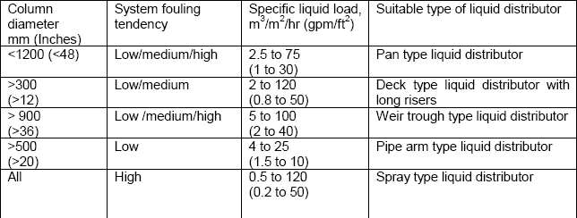
. It is important to distribute the liquid flow equally across the column area in order to secure an intensive mass transfer between the phases. Together with the head h o it allows the flow velocity at an outlet u o and thus the number of outlets required to be determined in distributors with liquid discharge or overflow. Liquid Distributor Design Calculation Liquid Distributor Design Calculation Bulan.
In process design perspective the 3-Phase separator is typically similar to the 2-phase separator but with additional internals to handle two immiscible liquids oil and water rather than one liquid. Molar flow rate 00094 KmolSec 2. H Height tangent to tangent of vessel m.
Mass flow rate 02778 KgSec Gas Density Mass flow rate Volumetric flow rate 11846 KgCum As of now basic detailing regarding flowrates is done and we need to go calculating the cross sectional area of the tower column. Both liquid and gas pipe distributors are covered. Unlike a plate column where the gas-liquid contact is stagewise a packed columns gas-liquid contact is continuous.
PDH Online PDH Center 5272 Meadow Estates Drive Fairfax VA 22030-6658 Phone Fax. The optimum drip point density increases with the nominal size of random packing. This Guide has been prepared for GBH Enterprises.
This will increase the liquid head needed to deliver the design. Volumetric flow rate 0234499 CumSec 3. Figure 3 shows the result of such a calculation for a trough with a width of b 100 mm for various flow velocities as a function of the liquid head h.
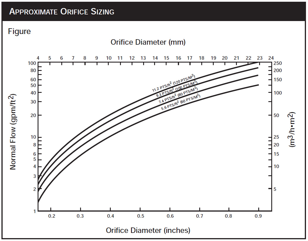
Considering 20 safety factor HETP 0. Column fluid dynamic calculations provide liquid and gas loads column diameter and type of packing. 7 indicates that the orifice coefficient can be as low as 062 and recommends use of a coefficient of 0707 for punched holes.
In determining the settling velocity in a liquid-liquid disper-. 4523 gpm 1027 m3hr During testing these measurements are checked for standard deviation where a coefficient of variation or Cv is calculated. Liquid maldistribution is a major issue in the design of packed columns.
The design rates for this application are shown as follows. 3971 gpm 902 m3hr Maximum flow. Operating range of VES distributor.
Using the calculation procedure described by Moore and Rukovena the quality of a distributor All the mod cons Part 2. 6640387966493070 For Educational Use. Vapor-side pressure drop across liquid distributor.
Note Number of side pipes adjusted to provide uniform entry per square foot of tower cross-section area. Typical design inlet liquid distributor using holes orifices on underside of distribution pipes. Optimum design for minimized material usage and high free space for gas flow.
Gas pipe distributors follow the same design steps as that for liquid pipe distributors except for some minor variations in the design procedure. An important design criteria is the number of drip points in. Articleosti_5611558 title Calculation of distributor grids in vessels with fluidized bed of ion exchange resin author Nikitina N I and Baryshnikova L G and Ksandopulo G G and Razumov I M and Terekhov N I abstractNote In fluidized processes the correct selection of a distributor device is critical.
Place determine the selection and design of equipment. The driving force promot-ing coalescence is gravity and in a given system is proportional to r g r being the density difference between the two liq-uid phases. The criterion of quality of the gas or liquid flow is the ratio of.
The standard design has a turndown ratio of 21 and the pressure drop in water is typically 02 06. The diameter of the droplets is a critical parameter. View of a sieve plate liquid distributor design of Raschig SOFTbank E-Book Center Tehran Phone.
The TUM-WelChem Cell Model is applied in liquid distributor design. Distributor Grosir Murah Liquid Distributor Design Calculation. 1985 gpm 451 m3hr Design flow.
Todays blog entry is meant to provide the stepwise calculations for a perforated pipe distributor including the design equations. Orifice pan liquid distributor with round or rectangular chimneys and a flat floor. Pharma Engineering For Engineer By Engineer.
This paper analyzes liquid distribution in a 0634 m random packed column. In packed column design the specification of liquid distributors and generally speaking column internals is one of the last steps. Distribution of the liquid onto the packed bed or structured packing is provided by appropriate liquid distributors.
Once the design of a liquid distributor has been completed and the distributor has been built it is advisable to carry out a distributor test. If higher turndown ratios are required taller risers can be used. An orifice typepan liquid distributor the most conventional type allows gas to pass the plate through risers while liquid flows through openings in the floor.
It covers neither guidance on the selection of trays and packings nor some aspects of their performance characteristics. 234 10 Design of distributors 22 i i 21 18 15 - 1 1-I 1 1 061 1 160 140 VT307-Hl at-lil Fig. For a perfectly square grid the highest possible is also the optimum wall spacing.
A distributor with a pressure drop of 30 the pressure drop due to the weight of the particles p CO2 ρ s gh 0 α s at U mf conditions is considered as a typical design point 79 and the. Liquid-phase Surface Tension 20dynecm Nortons Correlation Applicable Liquid Viscosity 35cP Nortons Correlation NOT applicable n 113080 Calculation ln HETP 08374366 HETP 23104368ft 07042211m For separations less than 15 theoritical stages a 20 design safety factor can be applied. A good rule of thumb is to design the liquid head at the minimum flow rate to be 2 in.
Box-type liquid distributor 0 2600 Liquid feed box Sieve plate Gas channel Fig. 1 SCOPE This Guide deals with the design and rating of packed distillation columns. Practical Design of Water Distribution Systems 2012 Instructor.
Q BA 2gP 1179d2 P1 2 1 Where q flow rate per perforation gpm B orifice coefficient assumed as 060 A area of orifice in2 g gravitational acceleration 322 fts2. A crucial parameter in the design of a distributor is the liquid load uL required for the separation process. Place determine the selection and design of equipment.
Holes at wall should be spaced on same basis. Liquid distribution in the packing is estimated in dependence of the liquid distributor design. Scrubber design for pharma scrubber calculations scrubber design.
With these specifications available liquid distributor design is conducted. The usual equation for flow through orifices is. Advice on both of these is given in GBHE- PEG-MAS-610 - Selection of Internals for.
Column Internals Explained Part 2 Separation Technologies

Column Internals Explained Part 2 Separation Technologies
A Side View Top And Lay Out Bottom Of Cross Type Liquid Download Scientific Diagram

A Side View Top And Lay Out Bottom Of Cross Type Liquid Download Scientific Diagram
Hanbit Soltech Products Packed Tower Internals
A Side View Top And Lay Out Bottom Of Cross Type Liquid Download Scientific Diagram
2

Column Internals Explained Part 2 Separation Technologies
0 comments
Post a Comment